CCNA 2 RSE Practice Skills Assessment – PT
CCNA Routing and Switching
Routing and Switching Essentials
Practice Skills Assessment – Packet Tracer
A few things to keep in mind while completing this activity:
- Do not use the browser Back button or close or reload any exam windows during the exam.
- Do not close Packet Tracer when you are done. It will close automatically.
- Click the Submit Assessment button in the browser window to submit your work.
Introduction
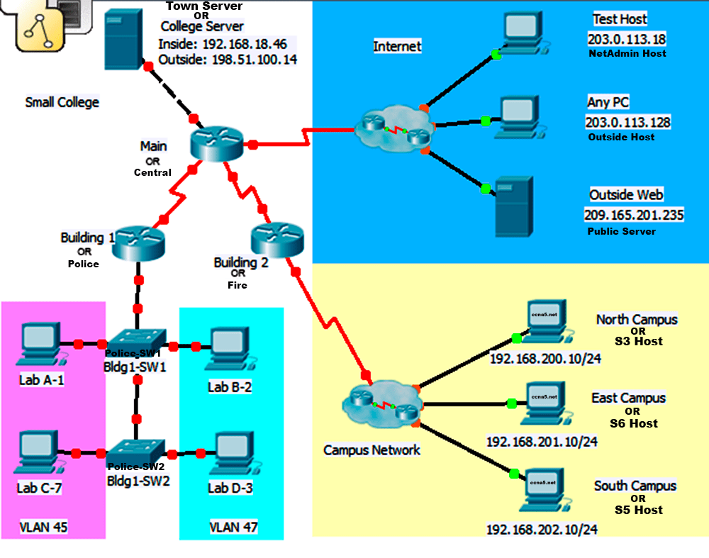
In this practice skills assessment, you will configure the Our Town network with single-area OSPFv2. In addition, you will configure router-on-a-stick routing between VLANs. You will also implement NAT, DHCP and access lists.
All IOS device configurations should be completed from a direct terminal connection to the device console.
Some values that are required to complete the configurations have not been given to you. In those cases, create the values that you need to complete the requirements. These values may include certain IP addresses, passwords, interface descriptions, banner text, and other values.
For the sake of time, many repetitive but important configuration tasks have been omitted from this activity. Many of these tasks, especially those related to device security, are essential elements of a network configuration. The intent of this activity is not to diminish the importance of full device configurations.
You will practice and be assessed on the following skills:
- Configuration of initial device settings
- IPv4 address assignment
- Configuration and addressing of router interfaces
- Configuration of a router as a DHCP server
- Implementation of static and dynamic NAT
- Configuration of the single-area OSPFv2 routing protocol
- Configuration of a default route and static summary routes
- Configuration of VLANs and trunks
- Configuration of routing between VLANs
- Configuration of ACL to limit device access
You are required to configure the following:
Police:
- Configuration of initial router settings
- Interface configuration and IPv4 addressing
- Configuration of DHCP
- Configuration of multiarea OSPFv2
- Configuration of routing between VLANs
Central:
- Interface configuration and IPv4 addressing
- Configuration of multiarea OSPFv2
- Configuration of IPv4 route summarization
- Configuration and propagation of a default route
- Configuration of static summary routes
- Configuration of static and dynamic NAT
- Configuration of ACLs
Fire:
- Interface configuration and IPv4 addressing
- Configuration of multiarea OSPFv2
- Configuration of a static summary route
Police-SW1:
- Configuration of VLANs
- Assignment of switch ports to VLANs
- Configuration of trunking
- Configuration of unused switch ports
Police-SW2:
- Configuration of VLANs
- Assignment of switch ports to VLANs
- Configuration of trunking
- Configuration of unused switch ports
Internal PC hosts:
- Configuration as DHCP clients
Addressing Tables
Note: You are provided with the networks that interfaces should be configured on. Unless you are told to do differently in the detailed instructions below, you are free to choose the host addresses to assign.
Addressing Table:
|
Device |
Interface |
Network |
Comments |
|
Police |
S0/0/0 |
192.168.10.104/30 |
any address in the network |
|
Gi0/0.45 |
192.168.45.0/24 |
first address in the network |
|
|
Gi0/0.47 |
192.168.47.0/24 |
first address in the network |
|
|
Gi0/0.101 |
192.168.101.0/24 |
first address in the network |
|
|
Central |
S0/0/0 |
192.168.10.104/30 |
any address in the network |
|
S0/0/1 |
192.168.10.112/30 |
any address in the network |
|
|
S0/1/0 |
198.51.100.0/28 |
first address in the network |
|
|
Gi0/0 |
192.168.18.40/29 |
first address in the network |
|
|
Fire |
S0/0/0 |
192.168.10.124/30 |
second address in the network |
|
S0/0/1 |
192.168.10.112/30 |
any address in the network |
|
|
Police-SW1 |
VLAN 101 |
192.168.101.0/24 |
any address in the network |
|
Police-SW2 |
VLAN 101 |
192.168.101.0/24 |
any address in the network |
Pre-configured addresses for reference:
|
Device |
Address |
|
Town Server |
192.168.18.46/29 |
|
NetAdmin Host |
203.0.113.18 |
|
Outside Host |
203.0.113.128 |
|
Public Server |
209.165.201.235 |
|
S3 Host |
192.168.200.10/24 |
|
S6 Host |
192.168.201.10/24 |
|
S5 Host |
192.168.202.10/24 |
VLAN Table:
|
VLAN Number |
VLAN Name |
VLAN Network |
Device:Port |
|
45 |
HR |
192.168.45.0/24 |
Police-SW1: Fa0/10 Police-SW2: Fa0/3 |
|
47 |
records |
192.168.47.0/24 |
Police-SW1: Fa0/15 Police-SW2: Fa0/21 |
|
101 |
comm |
192.168.101.0/24 |
SVI |
Instructions
All configurations must be performed through a direct terminal connection to the device consoles.
Step 1: Determine the Addresses to Assign
Determine the IP addresses that you will use for the required interfaces on the three routers and two switches. Use the information in the Addressing Table and follow the guidelines below:
- Assign the first IP addresses in the networks that are provided in the Addressing Table to the LAN interfaces.
- Assign the first address in the Central subnet to the interface that is connected to the Internet.
- Assign any valid host address in the networks that are provided in the Addressing Table to the serial interfaces.
- The host PCs will receive IP addresses over DHCP.
Step 2: Configure Police
- Configure Police with the following:
- Configure the router host name: PoliceDept
Router(config)# hostname PoliceDept
- Prevent the router from attempting to resolve command line entries to IP addresses.
PoliceDept(config)# no ip domain-lookup
- Protect privileged EXEC mode from unauthorized access with the MD5 encrypted password.
PoliceDept(config)# enable secret [password]
- Prevent device status messages from interrupting command line entries at the device console.
PoliceDept(config)# line con 0
PoliceDept(config-line)# logging synchronous
- Secure the router console and terminal lines.
PoliceDept(config)# line console 0
password [password]
login
PoliceDept(config)# line vty 0 4
password [password]
login
- Prevent all passwords from being viewed in clear text in the device configuration file.
PoliceDept(config)# service password-encryption
- Configure a message-of-the-day banner.
PoliceDept(config)# banner motd «message-of-the-day»
Step 3: Configure the Router Physical Interfaces
Configure the interfaces of the routers for full connectivity with the following:
- IP addresses as shown in the addressing table.
- Describe the operational Police serial interface. The Police Ethernet interfaces will be configured at the end of this assessment.
- DCE settings where appropriate. Use a rate of 128000.
PoliceDept(config)# interface Serial0/0/0
PoliceDept(config-if)#bandwidth 128
PoliceDept(config-if)#ip address 192.168.10.105 255.255.255.252
PoliceDept(config-if)#description Police and Central
PoliceDept(config-if)#clock rate 128000
PoliceDept(config-if)#no shutdown
Central(config)# interface Serial0/0/0
Central(config-if)#bandwidth 128
Central(config-if)#ip address 192.168.10.106 255.255.255.252
Central(config-if)#no shutdown
Central(config)# interface Serial0/0/1
Central(config-if)#bandwidth 128
Central(config-if)#ip address 192.168.10.114 255.255.255.252
Central(config-if)#clock rate 128000
Central(config-if)#no shutdown
Central(config)# interface g0/0
Central(config-if)#ip address 192.168.18.41 255.255.255.248
Central(config-if)#no shutdown
Central(config)# interface Serial0/1/0
Central(config-if)#ip address 198.51.100.1 255.255.255.240
Central(config-if)#no shutdown
Fire(config)# interface Serial0/0/1
Fire(config-if)#bandwidth 128
Fire(config-if)#ip address 198.51.100.1 255.255.255.240
Fire(config-if)#no shutdown
Step 4: Configure static and default routing
Configure the following static routes:
- Manually configure default routes to the Internet. Use the exit interface argument. All hosts on the internal LANs and School Network networks should be able to reach the Internet.
PoliceDept(config)#ip route 0.0.0.0 0.0.0.0 s0/0/0
Central(config)#ip route 0.0.0.0 0.0.0.0 s0/1/0
Fire(config)#ip route 0.0.0.0 0.0.0.0 s0/0/1
- It has been decided to use static routes to reach the branch networks that are connected to Fire. Use a single summary to represent the branch networks in the most efficient way possible. Configure the summary static route onCentral and Fire using the exit interface argument.
Central(config)#ip route 192.168.200.0 255.255.252.0 s0/0/1
Fire(config)#ip route 192.168.200.0 255.255.252.0 s0/0/0
Step 5: Configure OSPF Routing
Configure single-area OSPFv2 to route between all internal networks. The branch networks are not routed with OSPFv2.
- Use a process ID of 10.The routers should be configured in area 0.
- Use the correct inverse masks for all network statements. Do not use quad zero masks (0.0.0.0).
Step 6: Customize single-area OSPFv2
Customize single-area OSPFv2 by performing the following configuration tasks:
a. Set the bandwidth of the serial interfaces to 128 kb/s.
b. Configure OSPF router IDs as follows:
- Police: 1.1.1.1
- Central: 2.2.2.2
- Fire: 3.3.3.3
c. Configure the OSPF cost of the link between Police and Central to 7500.
d. Prevent routing updates from being sent out of any of the LAN interfaces that are routed with OSPFv2. Do not use the default keyword in the commands you use to do this.
Configuration step 5 and step 6
PoliceDept(config)#router ospf 10
PoliceDept(config-router)#router-id 1.1.1.1
PoliceDept(config-router)#network 192.168.10.104 0.0.0.3 area 0
PoliceDept(config-router)#network 192.168.45.0 0.0.0.255 area 0
PoliceDept(config-router)#network 192.168.47.0 0.0.0.255 area 0
PoliceDept(config-router)#network 192.168.101.0 0.0.0.255 area 0
PoliceDept(config-router)#passive-interface g0/0.45
PoliceDept(config-router)#passive-interface g0/0.47
PoliceDept(config-router)#passive-interface g0/0.101
PoliceDept(config)#interface s0/0/0
PoliceDept(config-if)#bandwidth 128
PoliceDept(config-if)#ip ospf cost 7500
Central(config)#router ospf 10
Central(config-router)#router-id 2.2.2.2
Central(config-router)#network 192.168.10.104 0.0.0.3 area 0
Central(config-router)#network 192.168.10.112 0.0.0.3 area 0
Central(config-router)#network 192.168.18.40 0.0.0.7 area 0
Central(config-router)#passive-interface g0/0
Central(config)#interface s0/0/0
Central(config-if)#bandwidth 128
Central(config-if)#ip ospf cost 7500
Central(config)#interface s0/0/1
Central(config-if)#bandwidth 128
Fire(config)#router ospf 10
Fire(config-router)#router-id 3.3.3.3
Fire(config-router)#network 192.168.10.112 0.0.0.3 area 0
Fire(config)#interface s0/0/1
Fire(config-if)#bandwidth 128
Step 7: Configure VLANs and Trunking
Configure Police-SW1 and Police-SW2 with VLANs and trunk ports as follows:
- Refer to the VLAN table above for the VLAN numbers and names that should be configured on both switches.
- Configure names for the VLANs. The VLAN names must be configured to match the names in the VLAN Table exactly (case and spelling).
On Police-SW1
Police-SW1(config)#vlan 45
Police-SW1(config-vlan)#name HR
Police-SW1(config)#vlan 47
Police-SW1(config-vlan)#name records
Police-SW1(config)#vlan 101
Police-SW1(config-vlan)#name comm
On Police-SW2
Police-SW2(config)#vlan 45
Police-SW2(config-vlan)#name HR
Police-SW2(config)#vlan 47
Police-SW2(config-vlan)#name records
Police-SW2(config)#vlan 101
Police-SW2(config-vlan)#name comm
- Configure the appropriate ports that link the switches and Police with the router as functioning trunk ports.
Police-SW1(config)#int g1/1
Police-SW1(config-if)#switchport mode trunk
Police-SW1(config-if)#no shutdown
Police-SW1(config)#int g1/2
Police-SW1(config-if)#switchport mode trunk
Police-SW1(config-if)#no shutdown
Police-SW2(config)#int g1/1
Police-SW2(config-if)#switchport mode trunk
Police-SW2(config-if)#no shutdown
- Assign the switch ports shown in the table as access ports in the VLANs as indicated in the VLAN Table.
Police-SW1(config)#int fa0/10
Police-SW1(config-if)#switchport mode access
Police-SW1(config-if)#switchport access vlan 45
Police-SW1(config-if)#exit
Police-SW1(config)#int fa0/15
Police-SW1(config-if)#switchport mode access
Police-SW1(config-if)#switchport access vlan 47
Police-SW1(config-if)#exit
Police-SW2(config)#int fa0/3
Police-SW2(config-if)#switchport mode access
Police-SW2(config-if)#switchport access vlan 45
Police-SW2(config-if)#exit
Police-SW2(config)#int fa0/21
Police-SW2(config-if)#switchport mode access
Police-SW2(config-if)#switchport access vlan 47
Police-SW2(config-if)#exit
- Address VLAN 101 on the network indicated in the VLAN Table. Note that the first address in this network will be assigned to the router in a later step in this assessment. The management interfaces of both switches should configured to be reachable by hosts on other networks.
Police-SW1(config)#ip default-gateway 192.168.101.1
Police-SW1(config)#interface vlan 101
Police-SW1(config-if)#ip address 192.168.101.2 255.255.255.0
Police-SW2(config)#ip default-gateway 192.168.101.1
Police-SW2(config)#interface vlan 101
Police-SW2(config-if)#ip address 192.168.101.3 255.255.255.0
- Configure all unused switch ports as access ports, and shutdown the unused ports.
Police-SW1(config)#int range fa0/1-9, fa0/11-14, fa0/16-24
Police-SW1(config-if-range)#switchport mode access
Police-SW1(config-if-range)#shutdown
Police-SW2(config)#int range fa0/1-2, fa0/4-20, fa0/22-24
Police-SW2(config-if-range)#switchport mode access
Police-SW2(config-if-range)#shutdown
Step 8: Configure DHCP
Police should be configured as a DHCP server that provides addressing to the hosts attached to Police-SW1 and Police-SW2. The requirements are as follows:
- Use VLAN45 and VLAN47 as the pool names. Note that the pool names must match the names given here exactly, all capital letters and exact spelling.
- Addresses .1 to .20 should be reserved for static assignment from each pool.
- The first address in each network will be assigned to the router interface attached to the networks as shown in the addressing table.
- Use a DNS server address of 192.168.18.100. This server has not yet been added to the network, but the address must be configured.
- Ensure that hosts in each LAN are able to communicate with hosts on remote networks.
PoliceDept(config)#ip dhcp excluded-address 192.168.45.1 192.168.45.20
PoliceDept(config)#ip dhcp excluded-address 192.168.47.1 192.168.47.20
PoliceDept(config)#ip dhcp pool VLAN45
PoliceDept(dhcp-config)#network 192.168.45.0 255.255.255.0
PoliceDept(dhcp-config)#default-router 192.168.45.1
PoliceDept(dhcp-config)#dns-server 192.168.18.100
PoliceDept(config)#ip dhcp pool VLAN47
PoliceDept(dhcp-config)#network 192.168.47.0 255.255.255.0
PoliceDept(dhcp-config)#default-router 192.168.47.1
PoliceDept(dhcp-config)#dns-server 192.168.18.100
*Set Clients to DHCP*
PC1, PC2, PC3, PC4
Step 9: Configure NAT
Configure NAT to translate internal private addresses into public addresses for the Internet. The requirements are:
a. Configure static NAT to the Town Server.
- Translate the internal address of the server to the address 198.51.100.14.
- Configure the correct interfaces to perform this NAT translation.
Central(config)#ip nat inside source static 192.168.18.46 198.51.100.14
Central(config)#interface g0/0
Central(config-if)#ip nat inside
Central(config)#interface s0/1/0
Central(config-if)#ip nat outside
b.Configure dynamic NAT (not NAT with overload, or PAT).
- Use the addresses remaining in the public address subnet of 198.51.100.0/28. The first two addresses in the subnet have already been assigned to the Central and ISP serial interfaces. Also, another address has already been used in the static mapping in the step above.
- Use a pool name of INTERNET. Note that the pool name must match this name exactly, in spelling and capitalization.
- Hosts on each of the internal LANs shown in the topology and on all of the branch networks should be permitted to use the NAT addresses to access the Internet.
- Use a source list number of 1.
- Your source list should consist of three entries, one each for the LANs and one for the branch networks.
BY Boogie
ip nat pool INTERNET 198.51.100.3 198.51.100.13 netmask 255.255.255.240
ip nat inside source list 1 pool INTERNET
ip nat inside source static 192.168.18.46 198.51.100.14
ip access-list standard 1
permit 192.168.45.0 0.0.0.255
permit 192.168.47.0 0.0.0.255
permit 192.168.200.0 0.0.3.255
Step 10: Configure Access Control Lists
You will configure two access control lists to limit device access on Central. You should use the any and host keywords in the ACL statements as required. The ACL requirements are:
a. Restrict access to the vty lines on Central:
- Create a named standard ACL using the name MANAGE. Be sure that you use this name exactly as it appears in these instructions (case and spelling).
- Allow only the NetAdmin Host to access the vty lines of Central.
- No other Internet hosts (including Internet hosts not visible in the topology) should be able to access the vty lines of Central.
- Your solution should consist of a single ACL statement.
b.Allow outside access to the Town Server while controlling other traffic from the outside. Create the ACL as directed below:
- Use access list number 101.
- First, allow NetAdmin Host full access to all network hosts and devices.
- Then, allow outside hosts to access the Town Server over HTTP only.
- Allow traffic that is in response to data requests from the internal and School Network hosts to enter the network.
- Add a statement so that counts of all denied traffic will be shown in the show access-lists command output.
- Your ACL should have only four statements.
Your ACL should be placed in the most efficient location possible to conserve network bandwidth and device processing resources.
Step 11: Configure Router-on-a-Stick Inter-VLAN Routing.
Configure Police to provide routing between the VLANs configured on the switches. As follows:
- Use the VLAN numbers for the required interface numbers.
- Use the first addresses in the VLAN networks for the interfaces.
PoliceDept(config)# interface g0/0
PoliceDept(config-if)#no sh
PoliceDept(config)# interface g0/0.45
PoliceDept(config-subif)#encapsulation dot1Q 45
PoliceDept(config-subif)#ip address 192.168.45.1 255.255.255.0
PoliceDept(config)# interface g0/0.47
PoliceDept(config-subif)#encapsulation dot1Q 47
PoliceDept(config-subif)#ip address 192.168.47.1 255.255.255.0
PoliceDept(config)# interface g0/0.101
PoliceDept(config-subif)#encapsulation dot1Q 101
PoliceDept(config-subif)#ip address 192.168.101.1 255.255.255.0
Step 12: Test and Troubleshoot Connectivity.
Ensure that the hosts attached to the VLANs can reach hosts on the School Network and the Internet.
Last Updated: November, 2013

Does anyone has the .pka?
te envio
can anyone help me… i accidentally disconnect the port connected from the central to the internet.. does anyone know what is the port connected to the internet??? T_T
ip nat pool INTERNET 198.51.100.3 198.51.100.13 netmask 255.255.255.240
ip nat inside source list 1 pool INTERNET
ip nat inside source static 192.168.18.46 198.51.100.14
ip access-list standard 1
permit 192.168.45.0 0.0.0.255
permit 192.168.47.0 0.0.0.255
permit 192.168.200.0 0.0.3.255
Part 10)
ip access-group 101 in
ip nat outside
access-list 1 permit 192.168.45.0 0.0.0.255
access-list 1 permit 192.168.47.0 0.0.0.255
access-list 1 permit 192.168.200.0 0.0.3.255
ip access-list standard MANAGE
permit host 203.0.113.18
access-list 101 permit ip host 203.0.113.18 any
access-list 101 permit tcp any host 198.51.100.14 eq www
access-list 101 permit tcp any any established
access-list 101 deny ip any any
Tom thnx for writing the solution , but i want to know where i want to configure this (step 10 ) ??
Thank you
Can anybody help solve step 9b please?
Can anybody to solve Step 10 ? I have already obtained 9 points within 13 points of Step 10.
Must be something like this:
!
interface Serial0/1/0
bandwidth 128
ip address 198.51.100.1 255.255.255.240
ip access-group 101 in
ip nat outside
!
access-list 1 permit 192.168.45.0 0.0.0.255
access-list 1 permit 192.168.47.0 0.0.0.255
access-list 1 permit 192.168.200.0 0.0.3.255
ip access-list standard MANAGE
permit host 203.0.113.18
access-list 101 permit ip host 203.0.113.18 any
access-list 101 permit tcp any host 198.51.100.14 eq www
access-list 101 permit tcp any any established
access-list 101 deny ip any any
!
line vty 0 4
access-class MANAGE in
password cisco
login
line vty 5 15
access-class MANAGE in
password cisco
login
!
I HAVE DONE ALL THE CONFIGS JUST NOW AND THE ACLS croco PUT HERE. sorry for the caps. had 93points from 100
feedback is this
Configure Named Standard ACL 0 2
Network:[[R2Name]]:ACL:MANAGE Incorrect
Configure Interface Addresses: R3 0 2
Network:[[R3Name]]:Ports:Serial0/0/1:IP Address Incorrect
Network:[[R3Name]]:Ports:Serial0/0/1:Subnet Mask Incorrect
Assign Switch Ports to VLANs: S2 0 2
Network:[[S2Name]]:Ports:FastEthernet0/3:Access VLAN Incorrect
Network:[[S2Name]]:Ports:FastEthernet0/21:Access VLAN Incorrect
Network:[[S1Name]]:Ports:FastEthernet0/10:Dynamic Mode Incorrect
Network:[[S1Name]]:Ports:FastEthernet0/15:Dynamic Mode Incorrect
Network:[[S2Name]]:Ports:FastEthernet0/21:Dynamic Mode Incorrect
Hello, you can let me ask is this contest PT how many to borrow.
Thank you
Hello!
Thanks for this.
Are you sure it is the Pratical Skills Exam ?
Can you share also the text of it and the network topology?
Thank you
I was going to ask the same question and I believe the above commands must be mastered because the Practical Skills Exam can be changed any time.
Thank you.
Hello, you guys ended up figuring out the network topology because there’s a few things that i cant get ..